This is the hardware part of the series. Parts 1 to 4 measure the arm's error in joint angles. This part builds the tool that will show the same error as ink on paper.
I want to make my SO-101 arm follow a path more accurately. For that, I need a way to see whether a change makes the path better or worse. Joint logs give me numbers, but numbers are easy to fool myself with. So I had an idea: put a pen on the arm and let it draw. When the arm leaves the path, the drawing goes wrong, and anyone can see it.
Today the pen is strapped into the gripper with tape. The gripper is taped shut, and its motor is off. It draws, but it raises a problem: the drawing shows the error of the arm plus the error of the strap. When the paper pulls on the tip, the pen moves in the strap. And I do not know exactly where the tip is. My best fit puts it about 110 mm from the gripper, with a 3.0 mm residual. That is larger than the error I want to see.
So the question of this article is simple: how do I hold a pen on the SO-101 so that the ink shows the arm's error, and not the holder's?
The answer: a sleeve on the stock finger
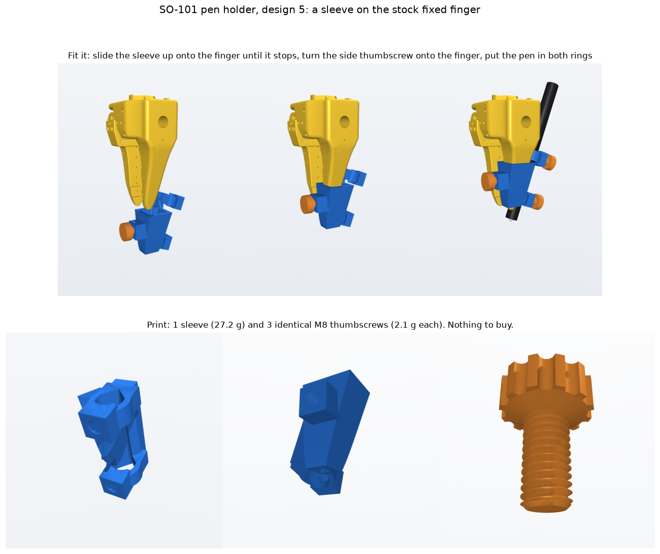
After five designs, my answer is a printed sleeve. It slides up onto the fixed finger of the stock gripper and holds the pen in two V clamps. You print 4 small parts: the sleeve and 3 identical thumbscrews. You buy nothing, and you do not take the arm apart. It takes any round pen from 8 to 13 mm, and the tip position is known for each pen.
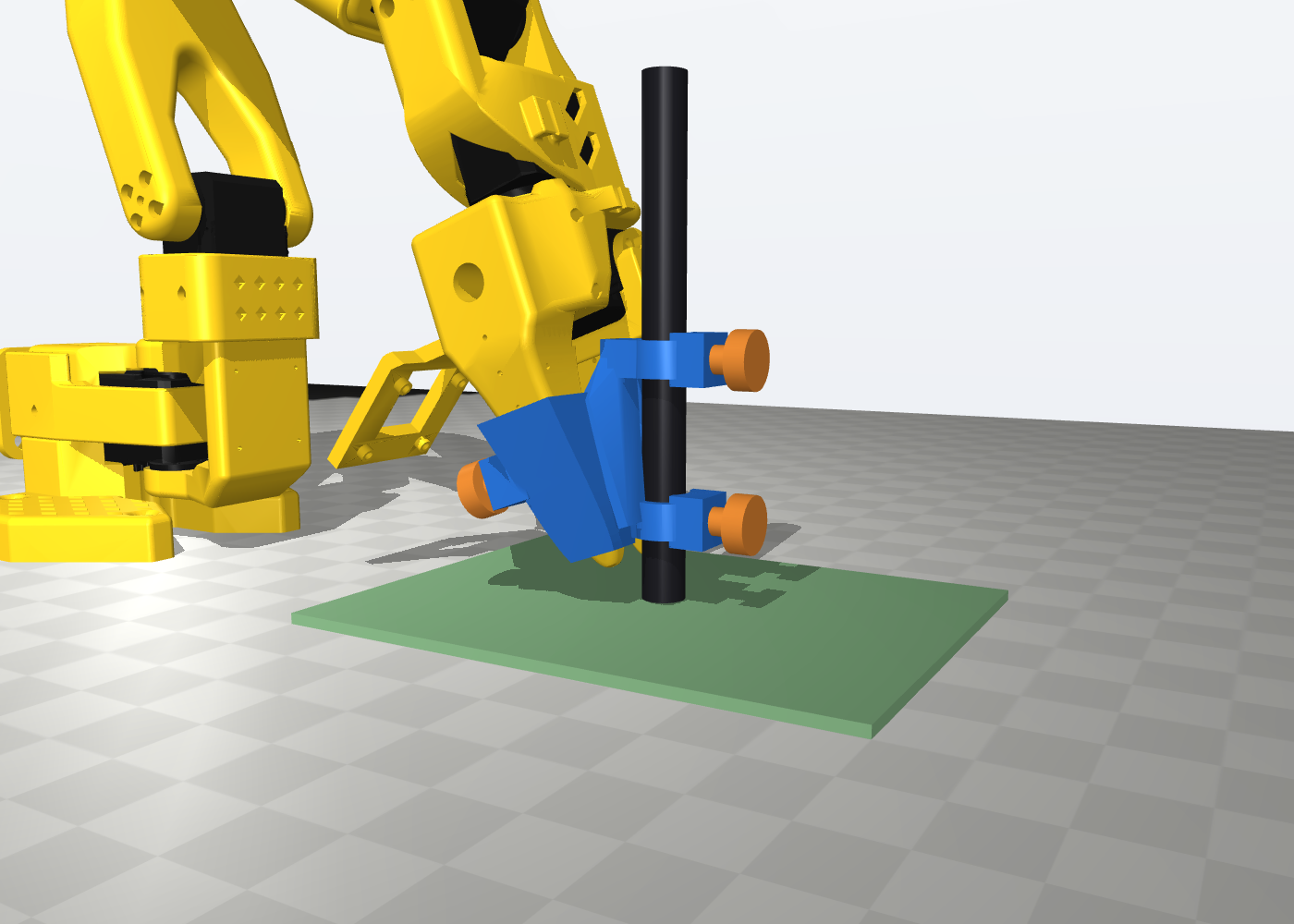
The design is open source: github.com/Hadrien-Cornier/so101-pen-holder. The repository has the STL files, the fitting steps, and a parametric CAD script that checks the parts against the stock gripper. The first set is printed in PLA, and the sleeve is on my arm. It slid onto the finger and the screws turned in on the first try, with no change to the design. I felt no play by hand. The two videos below show the print and the holder on the arm. I have not measured anything yet, so every number in this article is still a design value.
The videos are not test results. They show no drawing and no tablet reading. I have not measured the play at the tip, the tip position, or the hold of the sleeve yet. I felt no play by hand, but that is not a measurement. The tests are in the last section. I bought the tablet to measure where the pen tip goes, and the README of the repository explains why.
The rest of this article explains how I got there, and why each design failed or lost.
What the holder must do
I wrote the requirements before I looked for a design. Each one removes one source of error that is not the arm, or one reason why nobody would use the holder:
| Requirement | Goal | Why |
|---|---|---|
| Rigid | under 0.1 mm of play at the tip at 0.5 N | The paper drag must not move the pen in the holder. |
| Repeatable | under 0.2 mm spread when I take the pen out and put it back | After I change the pen, it must go back to the same place. |
| Tip set by construction | the tip at a known point, near the wrist_roll axis | The model must know the tip position without a 3 mm guess. |
| Any common pen | an ink pen and a Wacom pen, at least | I also want a drawing tablet under the pen later. A Wacom tablet senses only its own pen. |
| Easy to copy | nothing to buy, no change to the arm, a small print | Anybody with an SO-101 should be able to try it. |
| Light | near the mass of the present pen and strap | Each 10 g at the end of the arm changes the shoulder sag by 2 to 4 mrad. |
My first list also had a vertical slide, so that the pen rests on the paper by its own weight, and one keyed sleeve for each pen. I removed both later. The section on design 3 explains why.
Why is 0.1 mm the goal? A joint error moves the tip by the error times a lever, and the lever is long. In a typical drawing pose, 240 mm in front of the base, an error of 1 mrad on every joint moves the tip by about 0.3 mm. With the joint errors of my best model from part 4, I predict a drawing error of about 1.2 mm RMS. The holder must stay well below that, or I measure the holder.
Five designs
I found grippers and camera mounts for the SO-100 and the SO-101, but no pen holder. I searched GitHub, the official SO-ARM100 repository, Printables, Thingiverse, MakerWorld, Cults3D and the LeRobot forum. So I designed one, five times. The picture shows all five on the same gripper with the same camera.
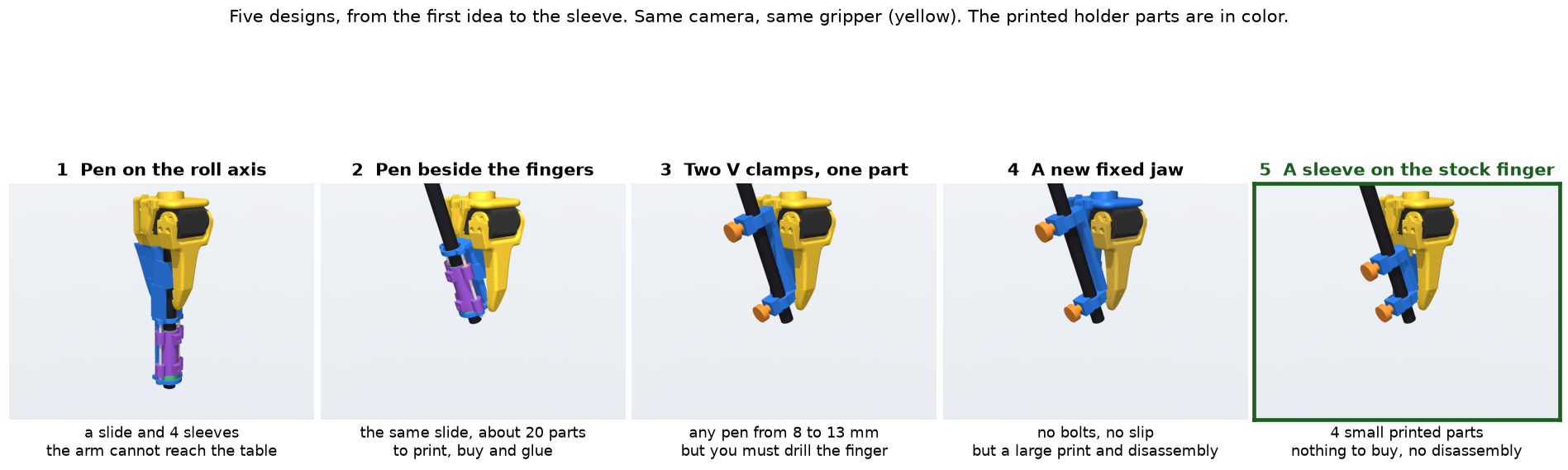
Design 1: the pen on the roll axis
The last joint of the arm turns the gripper about its own axis (wrist_roll). My first idea was to put the pen on that axis, between the fingers. The tip position then has only one unknown, its distance along the axis, and the drag of the paper cannot turn that joint.
The pen hung in a carriage that slid on two steel shafts through bronze bushings, so that it rested on the paper by its own weight. A bracket clamped the shafts onto the fixed finger with two M2 bolts. Each pen had its own printed sleeve.
The lever rule for the slide
A bushing must be a little larger than its shaft, or the carriage cannot slide. That small gap is the clearance, c. When the paper drag pushes the tip to the right, the carriage moves across the clearance and tilts. When the drag reverses, it tilts the other way.
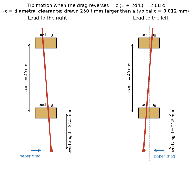
With a span L between the two bushings and an overhang d from the lower bushing to the tip, the tip moves by:
So the span must be long, the overhang short, and the clearance small. With 3 mm ground shafts and sized bushings, c is 0.004 to 0.020 mm, and the tip moves 0.016 to 0.049 mm. The same rule is the reason why the later designs hold the pen at two points far apart.
The design passed every collision check on the gripper alone. Then I put it on the full arm model, and two problems appeared.
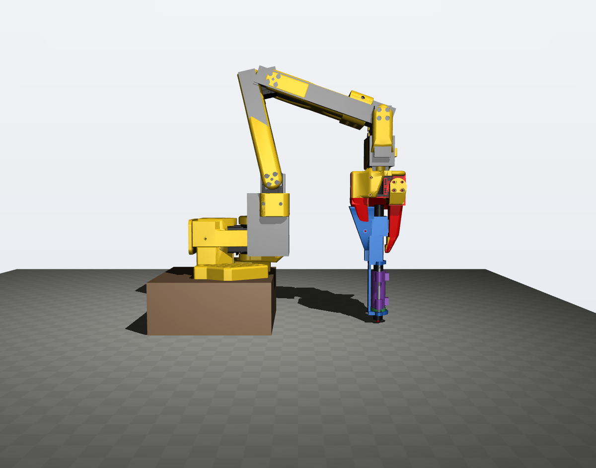
First, the arm cannot reach paper that is level with its base. The tip is 196 mm below the gripper, and with the wrist pointing down, the wrist_flex joint reaches its limit. The base needs a riser of at least 30 mm.
Second, the long tip makes every joint error bigger on the paper. For a joint that turns about a horizontal axis (shoulder_lift, elbow_flex and wrist_flex), the lever is the height of that joint above the tip. With the wrist high above a long pen, the wrist and elbow levers are long. At 240 mm from the base, 1 mrad of error on every joint moves the tip of design 1 by 0.42 mm.
Every way to hold the pen
So I compared every way that I could find to attach the pen. For each one, a script finds the tip position nearest to the gripper that keeps the fingers above the paper and the pen clear of the gripper. Then it maps where the arm can reach the paper with the pen vertical, and it calculates the tip error for 1 mrad on every joint.
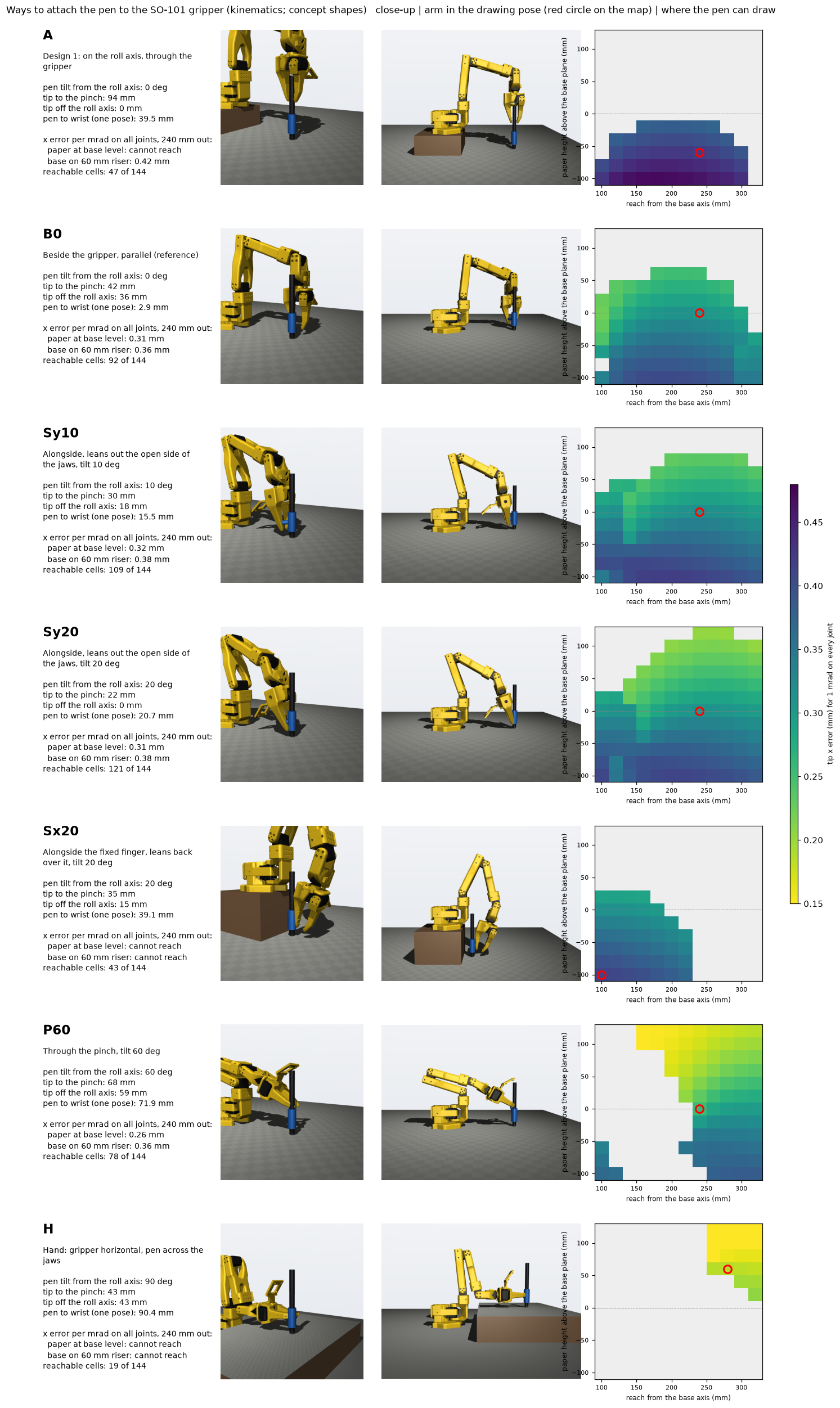
The table compares the layouts at 240 mm from the base, with the paper level with the base:
| Layout | How the pen attaches | Tip to the pinch | Tip error per mrad |
|---|---|---|---|
| A | Design 1: on the roll axis, through the gripper | 94 mm | cannot reach |
| B0 | Beside the gripper, fully parallel | 42 mm | 0.31 mm |
| Sy10 | Beside the fingers, tilted 10° out of the open side of the jaws | 30 mm | 0.32 mm |
| Sy20 | Beside the fingers, tilted 20° out of the open side of the jaws | 22 mm | 0.31 mm |
| Sx20 | Beside the fixed finger, tilted 20° over its back | 35 mm | cannot reach |
| P60 | Through the pinch, tilted 60° | 68 mm | 0.26 mm |
| H | Like a hand: gripper horizontal, pen across the jaws | 43 mm | cannot reach |
The "pinch" is the point between the two fingertips, where the gripper holds an object. The comparison taught me four things:
- The tip cannot be at the pinch. The fingers extend past it, so they would touch the paper first.
- The hand layout has the shortest levers, but it cannot reach. With the gripper horizontal, the joint limits let the pen touch the paper only far from the base.
- A tip near the pinch is not the same as a short lever. Sy20 has its tip nearest to the pinch, but the gripper stays almost vertical, so the wrist stays high.
- The direction of the tilt matters. A pen that leans over the fixed finger (Sx20) needs the wrist to roll almost half a turn, past the joint limit.
I chose Sy20. It reaches the largest area of paper, it needs no riser, and its tip stays about 6 mm from the roll axis, so a wrist_roll error barely moves it. Every later design keeps this layout.
Design 2: the pen beside the fingers
Design 2 put the slide of design 1 in the Sy20 layout. It passed its checks after two fixes: I moved the guide 6 mm out of the jaws, because the carriage hit the fingertips, and I made the spine thicker, because one section was only 41.6 mm².
It worked on paper, but it was not a design that anybody else would build. With the bracket, the carriage, the sleeves, two ground shafts, four bushings, the bolts and the glue, it had about 20 parts. The two holds on the pen were only 31 mm apart, and the bushings still left 0.016 to 0.049 mm of play.
Design 3: two V clamps on one part
So I asked what each part did, and whether something simpler could do the same job.
The slide. The slide let the pen rest on the paper with a constant force, because the paper is not flat and the arm height is not exact. A soft pad under the paper does the same job: the arm presses the tip 2 mm into a 3 mm pad, and the pad takes up the height error. A fixed pen needs no shafts and no bushings, and it has no clearance to tilt across. The cost is that the contact force now changes with the arm height. That matters for the Wacom pen, which measures pressure, so one of my tests checks it.
The sleeves. One sleeve for each pen was a way to put every pen in the same place. A V clamp does this for every pen at once. The clamp is a ring with a 90° V on the gripper side and a thumbscrew on the other side. The screw pushes the pen into the V, so the pen touches the V on two lines and can sit in only one place. A thinner pen sits deeper in the V, and its axis moves toward the gripper by a known distance:
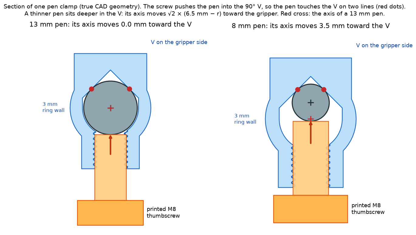
The screws. At first the thumbscrews were metal screws in heat-set inserts. Then I asked whether the screws could be printed too. An M3 thread cannot print well: its pitch is 0.5 mm, so a 0.2 mm layer gives each turn only 2.5 layers. An M8 thread has a 1.25 mm pitch, and FDM printers make it well. So each clamp now has a printed M8 thread and a printed thumbscrew. The load that the clamp must resist is small (the paper drag is about 0.5 N), so a plastic thread is strong enough.
Design 3 was one printed part with two clamps 80 mm apart. Then I asked the obvious question: what keeps it from sliding down the finger? The answer was two M2 bolts through two holes in the finger. When I measured those holes in the mesh, they were only 1.5 by 1.8 mm. An M2 bolt does not fit. Every user would have to drill two holes in their robot.
Design 4 and the last choice
The way to remove the bolts is to print the clamps and the finger as one part. In design 4, I joined the clamps to the official print STL of the fixed jaw. It matches my simulation mesh with a mean gap of 0.0035 mm. Nothing can slip, and all its checks pass. But it is the largest print of the gripper, and you must take the gripper apart to change it.
So I made the last choice between three ways to attach the same clamps:
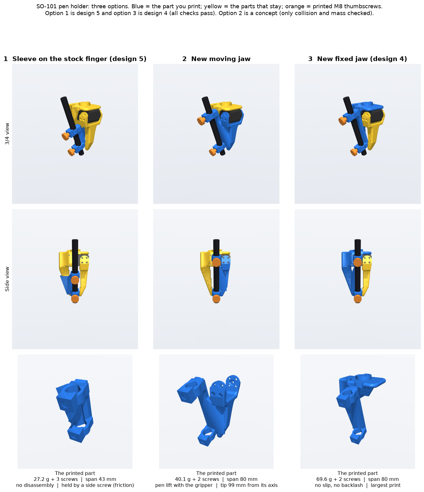
| Sleeve on the finger | New moving jaw | New fixed jaw (design 4) | |
|---|---|---|---|
| Printed plastic | 34 g | 44 g | 74 g |
| Take the gripper apart | no | the moving jaw | the full gripper |
| Hold on the arm | wedge seat and friction | jaw screws | jaw screws |
| Play at the tip | none in the clamps | the backlash of the gripper motor | none |
| Distance between the clamps | 43 mm | 80 mm | 80 mm |
The moving jaw was tempting, because the gripper motor could lift the pen off the paper between strokes. But its tip is 99 mm from the axis of the gripper motor. If the motor has 0.5° of backlash (a value that I assume, not measure), the tip moves by about 0.9 mm, unless the jaw always presses on a stop.
I chose the sleeve. It is the smallest print. It needs no tools and no change to the arm, so anybody with an SO-101 can try it in an afternoon. That makes it the right design to release.
Design 5: the sleeve on the stock finger
The sleeve is a hollow block with the shape of the end of the fixed finger. You slide it up onto the finger until it stops, and you turn a side thumbscrew onto the finger.
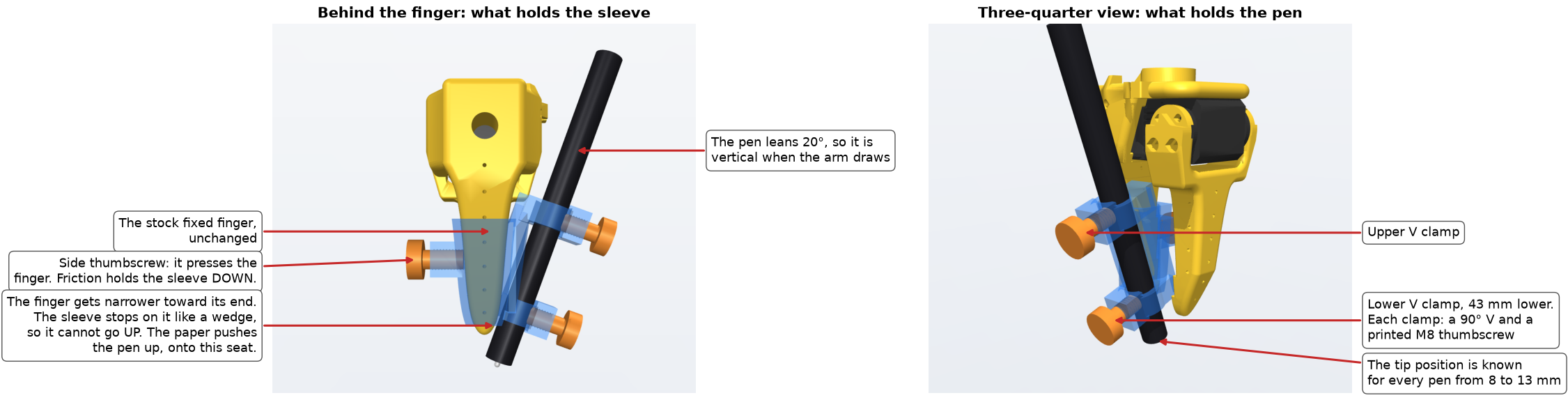
It holds in three directions:
- Up: the finger gets narrower toward its end. The sleeve stops on it like a wedge. The paper pushes the pen up, which pushes the sleeve harder onto this seat. The main load makes the hold tighter.
- Down: the side thumbscrew presses one side of the finger and pushes the other side against the inner wall of the sleeve. Friction on both sides holds the sleeve. I estimate 30 to 60 N of hold against a weight of about 0.45 N, but this is the weakest point of the design: nothing locks the sleeve positively in this direction.
- Sideways: the pocket fits the finger with 0.15 mm of clearance. The side screw and the wedge seat remove it.
The finger is short, so the two clamps are 43 mm apart instead of 80 mm. The clamps have no play, but a shorter span makes the pen less stiff against tilt. I have not calculated that bending yet.
Because the V clamps adapt to the pen, the tip position depends on the pen diameter. The table gives the tip in the frame of the gripper body of the MuJoCo model:
| Pen | Diameter | Tip position (x, y, z) | Tip off the roll axis |
|---|---|---|---|
| 13 mm pen | 13.0 mm | (0, −6.00, −120.00) mm | 6.00 mm |
| Wacom Pen 4K | 12.0 mm | (0, −5.34, −119.76) mm | 5.34 mm |
| BIC 4-Colour | 11.6 mm | (0, −5.07, −119.66) mm | 5.07 mm |
| Pilot V5 | 10.6 mm | (0, −4.41, −119.42) mm | 4.41 mm |
| 8 mm pen | 8.0 mm | (0, −2.68, −118.79) mm | 2.68 mm |
The tip and the pen direction are the same as in design 2. So the joint levers, and the predicted drawing error of about 1.2 mm RMS, do not change.
The five designs side by side
| Design 1 | Design 2 | Design 3 | Design 4 | Design 5 | |
|---|---|---|---|---|---|
| Layout | roll axis | Sy20 | Sy20 | Sy20 | Sy20 |
| Holds the pen | slide, 1 sleeve per pen | slide, 1 sleeve per pen | 2 V clamps, 80 mm apart | 2 V clamps, 80 mm apart | 2 V clamps, 43 mm apart |
| Parts | about 20 | about 20 | 3 printed, 2 bolts | 3 printed | 4 printed |
| Change to the arm | drill 2 holes | drill 2 holes | drill 2 holes | new fixed jaw | none |
| Paper at the base level | cannot reach | reaches | reaches | reaches | reaches |
| Why it lost | reach | too many parts | drilling | large print, disassembly | chosen |
How I built and checked the designs
Each design is one Python script with build123d and manifold3d. The script reads the stock gripper meshes, builds every part from parameters, and checks for collisions:
- the holder against the fixed jaw, the jaw motor and the moving jaw over its full opening range;
- the holder along the path where it slides onto the finger;
- six pens from 8 to 13 mm against the holder and the gripper;
- each printed screw, turned in with its thread in phase with the hole, against the holder and the gripper.
The checks also found errors in my own work. A collision test that used only the corners of the meshes let a pen pass through a flat face of the gripper, and it made one layout look much better than it was. I replaced it with a test against the surfaces.
When I drew the clamp section for this article, I found a thin wall. Near its base, the free space of the V was wider than any pen needs, and it left the ring only 0.7 mm thick at two points, where the screw force passes. I cut the free space to the bore width, and the ring is now 3 mm thick everywhere. A wall-thickness scan of the whole sleeve now finds only one thin area: a 0.85 mm skin between the finger and the pen, which carries almost no load.
The public repository has a standalone version of the design 5 script. In a new Python environment, it makes STL files that are byte for byte the same as mine.
What I will test
The first set is printed, and test 1 passed by hand. Next I do the other tests:
- Thread fit: done by hand. The screws turned in on the first try, so I did not change the thread clearance.
- Play: a 51 g weight pulls the pen to each side, and a dial indicator reads the tip. Goal: under 0.1 mm.
- Repeatability: I take the pen out and put it back 10 times, and make a dot each time. I scan the dots. Goal: under 0.2 mm spread.
- Hold: I hang a 500 g weight (about 5 N) from the sleeve and check that it does not slip down the finger.
- Contact: I replay one motion in the air and one on the pad. If the joint errors are the same, the fixed pen and the pad are enough.
- Tip position: I turn only the roll joint with the pen on the paper. The tip draws a small arc. Its radius should be the offset in the table, for example 5.34 mm for the Wacom pen.
The numbers in this article are design values from CAD and the arm model. None of them is measured yet. In the next post I will show the measured play and the first drawings, and whether the ink makes the arm's errors as obvious as I hope.